
A points ignition system, often referred to as a breaker-point ignition, is one of the oldest and most fundamental technologies found in classic cars, vintage motorcycles, and older small-engine equipment.
While modern vehicles have largely transitioned to electronic ignition systems, millions of classic vehicles and machines still rely on the reliable yet delicate mechanics of the points-based setup.
At the heart of this system lies a precise interaction between the ignition coil, condenser, distributor, and the contact points themselves all working in harmony to generate the high-voltage spark needed to ignite the air-fuel mixture inside the combustion chamber.
A weak spark is one of the most frustrating and elusive problems a mechanic or hobbyist can face. It can cause hard starting, misfires, poor fuel economy, rough idle, and even complete engine failure.
The challenge is that weak spark symptoms often mimic other engine problems, making accurate diagnosis essential before replacing parts unnecessarily.
Whether you’re restoring a vintage muscle car, tuning a classic motorcycle, or troubleshooting a lawn tractor, understanding how to properly diagnose a weak spark in a points ignition system is an invaluable skill. This guide covers the top 10 most effective diagnostic methods, each explained in detail to help you identify the root cause with confidence.
1. Perform a Visual Spark Test
The first and most straightforward step in diagnosing a weak spark is performing a direct visual spark test. This foundational technique requires minimal tools and provides immediate feedback about the health of your ignition system.
Before diving into complex electrical measurements or component disassembly, a simple spark test can confirm whether the system is producing spark at all and give you a rough idea of its strength.
To perform the test, begin by removing a spark plug wire from one of the engine’s spark plugs. Insert a known good spark plug into the end of the wire and ground the plug’s metal body firmly against a metal part of the engine block or chassis.
Make sure the plug is making solid metallic contact a poor ground connection will give you a false reading. Next, have an assistant crank the engine while you observe the spark plug gap in a low-light environment if possible, as this makes the spark more visible.
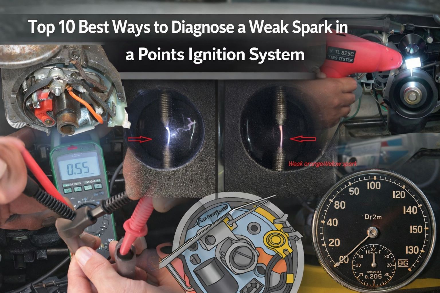
A healthy ignition system should produce a bright, consistent, blue-white spark that jumps the plug gap with authority. The spark should appear sharp and crisp, not lazy or irregular. If you observe a weak, orange, yellow, or intermittent spark, this is a clear indicator that something within the ignition system is not functioning correctly.

The color and intensity of the spark are telling. A bright blue spark indicates high voltage being delivered effectively. An orange or reddish spark typically signals low voltage output, which can be caused by a failing ignition coil, worn contact points, a faulty condenser, or high resistance somewhere in the secondary circuit. A yellow spark may also indicate carbon tracking or moisture contamination in the distributor cap or plug wire.
It’s important to compare the spark against a known good standard. If you have access to a spark tester tool a specialized device with an adjustable air gap you can measure the spark’s ability to jump increasingly wider gaps. A strong ignition system should be capable of jumping a gap of at least 3/8 to 1/2 inch under no-load conditions.
One important safety note: always keep the grounded plug away from the carburetor or any fuel source, as a spark near flammable vapors can cause a fire or explosion. Perform this test in a well-ventilated area.
This initial visual test sets the stage for all further diagnostics. If the spark appears weak during this test, you now have confirmation that the issue lies within the ignition system rather than fuel delivery, compression, or timing and you can proceed with the more targeted tests that follow.
2. Inspect and Measure the Contact Points Gap
The contact points are the mechanical heart of the points ignition system, and an incorrect gap is one of the most common causes of weak or unreliable spark.
The points open and close in sync with engine rotation, interrupting the primary circuit of the ignition coil to induce the high-voltage pulse needed for ignition. If the gap is too large or too small, the entire timing and energy transfer of the system is compromised.
To inspect the points, begin by removing the distributor cap by releasing its retaining clips or screws. Set it aside carefully, noting the orientation of the rotor and cap for reinstallation. With the cap removed, you’ll see the rotor on top of the distributor shaft. Remove it by pulling straight up. Below, you’ll find the contact points assembly typically consisting of a fixed contact and a movable arm tipped with tungsten contacts.
Visually inspect the contact surfaces first. Healthy points should be relatively flat, smooth, and grayish in color. Look for signs of pitting, burning, erosion, or a blue-black discoloration that indicates excessive arcing.

A small amount of wear is normal, but heavily pitted or transferred material on the contacts drastically reduces the system’s ability to make a clean electrical connection and disrupts the collapse of the coil’s magnetic field.
To measure the gap accurately, you’ll need a feeler gauge. Rotate the engine (by hand or using the starter briefly) until the rubbing block of the points arm sits on the highest point of one of the distributor cam lobes this is when the points are at maximum opening. Slide the appropriate feeler gauge blade between the open contacts.
Most classic vehicles specify a gap between 0.014 and 0.016 inches (approximately 0.35 to 0.40 mm), but always consult your vehicle’s service manual for the exact specification.
If the gap is incorrect, loosen the locking screw on the fixed contact plate and adjust accordingly. Too small a gap means the points stay closed too long, reducing the dwell angle and potentially causing the coil to overheat. Too large a gap means the points open too quickly, shortening the dwell angle, reducing the coil’s saturation time, and producing a weak spark.
A well-adjusted points gap is the foundation of a healthy ignition system. Even minor deviations can have outsized effects on spark quality, particularly at higher engine RPMs where the system has less time to complete each ignition cycle.
3. Check the Dwell Angle with a Dwell Meter
While a feeler gauge gives you a static measurement of the points gap, a dwell meter takes your diagnostic capability to the next level by measuring the dwell angle the number of degrees of distributor rotation during which the points remain closed. This is a dynamic measurement taken while the engine is running or cranking, and it directly reflects the actual behavior of the points during operation.
Dwell angle is critically important because it determines how long the ignition coil has to build up its magnetic field (a process called saturation) before the points open and the field collapses to generate the high-voltage spark. Too little dwell means insufficient coil saturation and a resulting weak spark. Too much dwell can cause overheating of the coil and points.
To use a dwell meter, connect the positive lead to the distributor side of the points (or the negative terminal of the coil, which connects to the same circuit) and the negative lead to a good chassis ground. Set the meter to the appropriate cylinder setting most meters have positions for 4, 6, and 8-cylinder engines. Start the engine and allow it to idle.

Read the dwell angle from the meter. Typical specifications for a 4-cylinder engine might be around 50–58 degrees, while a V8 might call for 28–32 degrees, depending on the number of distributor cam lobes. Each lobe represents one ignition cycle, so more cylinders mean smaller dwell angles.
If the dwell reading is unstable jumping around or fluctuating as the engine runs this points to worn distributor bushings that allow shaft wobble, a damaged cam, or weak points arm spring tension. An inconsistent dwell angle produces inconsistent spark timing and energy, which directly causes misfires and rough running.
After adjusting the points gap, always recheck with the dwell meter running, as dynamic measurements often differ slightly from static feeler gauge readings. Fine-tune your gap adjustment until the dwell stabilizes at the specified value. A stable, correct dwell angle is one of the surest signs that your points ignition system is in good health and capable of producing strong, consistent spark.
4. Test the Ignition Coil Output Voltage
The ignition coil is the voltage transformer of your ignition system, converting the battery’s 12 volts into the 20,000 to 40,000 volts needed to jump the spark plug gap. A weak or failing coil is a primary suspect when diagnosing weak spark, and testing it properly is essential to ruling it out or confirming it as the source of the problem.
Begin with a basic resistance test using a digital multimeter. With the coil disconnected from the circuit, measure the primary winding resistance by placing the multimeter probes on the two small terminals of the coil (positive and negative). Primary resistance for most classic ignition coils should fall between 1.5 and 3.5 ohms. A reading significantly outside this range particularly much higher indicates a damaged winding.
Next, test the secondary winding resistance by placing one probe on the coil’s high-voltage tower (the large center terminal where the coil wire connects to the distributor cap) and the other probe on either small terminal. Secondary resistance should typically fall between 6,000 and 12,000 ohms, though this varies by coil design and manufacturer specifications.
For a more practical output test, use the spark gap method described in Method 1, but this time use an adjustable spark tester. Crank the engine and gradually widen the test gap until the spark can no longer bridge it. A strong coil should bridge a gap of at least 1/2 inch. A coil that struggles to jump even 1/4 inch under no-load conditions is definitely underperforming.
It’s also worth checking for heat-related coil failure. Some coils produce adequate spark when cold but deteriorate rapidly once they reach operating temperature. If the engine starts well but develops misfires after warming up, conduct your spark tests both cold and after a period of running to compare.
Coil failure is often gradual rather than sudden. A coil operating at reduced efficiency may pass basic resistance tests but still fail to produce adequate voltage under the load of actual engine compression. Replacing a suspect coil with a known good unit and retesting is sometimes the most reliable final confirmation.
Also Read: 5 Classic Muscle Cars That Survived the Fuel Crisis vs 5 That Didn’t
5. Inspect and Test the Condenser
The condenser (also called a capacitor) is a small but critically important component in the points ignition system, yet it is frequently overlooked during diagnostics.
Its primary function is to absorb the surge of current when the points open, preventing the points from arcing excessively and allowing the coil’s magnetic field to collapse rapidly which is what generates the high-voltage spark. A faulty condenser is one of the most common causes of weak or intermittent spark in a points system.
Signs of a failing condenser include burned or pitted contact points (even on newly installed sets), weak or yellow spark, engine misfires that worsen with RPM, and a distributor cap that shows evidence of internal arcing or carbon tracking.

Testing a condenser accurately requires either a dedicated condenser tester or a capacitance meter. The condenser should be disconnected from the circuit before testing. A good condenser for most automotive applications will measure between 0.18 and 0.25 microfarads. A reading significantly outside this range or an open-circuit reading indicates the condenser is defective.
If you don’t have a condenser tester, a quick field test can be performed with a multimeter set to the resistance (ohms) function. Connect the probes to the condenser’s terminal and body. You should see the resistance reading climb from a low value and then stabilize at a high value as the condenser charges. If it reads zero ohms (short circuit) or immediately reads infinite resistance without any climbing behavior, the condenser is faulty.
Because condensers are inexpensive and their failure is so common, many experienced mechanics replace the condenser whenever they install new contact points. Given that a bad condenser will destroy a new set of points within hours of running, this is a sound preventive strategy. Always ensure the condenser mounting bracket makes solid electrical contact with the distributor housing to provide a proper ground.
6. Measure Primary Circuit Voltage Drop
Voltage drop testing is one of the most diagnostic yet underutilized techniques for diagnosing weak spark. Even if every component in the ignition system is individually within specification, excessive resistance in the wiring, connections, or switch can rob the system of the voltage it needs to function properly. A volt drop test identifies exactly where that resistance exists.
With the ignition switched on (but engine not running), connect a digital multimeter between the positive battery terminal and the positive terminal of the ignition coil.
The reading should be very close to battery voltage ideally within 0.3 to 0.5 volts. A larger drop indicates resistance in the feed circuit dirty connections, a failing ignition switch, a corroded ballast resistor, or damaged wiring.
Repeat the measurement from the coil’s negative terminal to a chassis ground with the points closed (you can hold them closed manually or use a jumper wire).

Again, any reading above 0.2 volts indicates unwanted resistance in the ground circuit, which reduces current flow through the primary winding and weakens coil output.
Pay special attention to the ballast resistor, which is present in many points ignition systems. This resistor reduces voltage to the coil during normal running to prolong coil and points life.
It is typically bypassed during cranking to ensure full voltage reaches the coil for starting. A faulty or incorrect ballast resistor can reduce the coil’s input voltage significantly, leading to weak spark at all speeds.
Systematically tracing voltage drops through the primary circuit reveals hidden resistances that would never be detected by simple component substitution. This method turns an otherwise mystery problem into a precise, locatable fault.
7. Inspect Spark Plug Wires and Distributor Cap
High-resistance or damaged spark plug wires and a cracked or carbon-tracked distributor cap can strangle even a powerful ignition system, resulting in weak, misfiring, or absent spark at individual cylinders. These components are part of the secondary (high-voltage) circuit and are often neglected during routine maintenance.
Use a digital multimeter set to resistance and measure each spark plug wire individually. Remove the wire from both the distributor cap and spark plug before testing. Resistance should typically be between 10,000 and 15,000 ohms per foot of wire length. Wires with resistance exceeding 25,000 ohms per foot or showing an open circuit are defective and should be replaced.

Inspect each wire’s insulation carefully for cracks, burns, or carbon tracking black lines running along the outside of the wire where high voltage has been arcing to ground. Damaged insulation causes the high-voltage pulse to short to ground before reaching the plug, resulting in a weak or absent spark.
Remove and carefully examine the distributor cap under good lighting. Look for carbon tracking (hairline black lines running between terminals), cracks in the cap body, corrosion on the internal brass terminals, or a worn or burned center contact.
Even tiny cracks allow moisture to collect inside the cap, dramatically reducing spark voltage. Carbon tracks provide an alternative low-resistance path for the high voltage to follow instead of going to the correct plug wire.
Replacing a cap with any visible tracking or cracking is mandatory no amount of cleaning will permanently fix a carbon track once it has formed. Use a quality replacement cap that matches the original specifications.
8. Check Ignition Timing
Incorrect ignition timing doesn’t reduce the voltage of the spark itself, but it directly affects when the spark fires in relation to piston position and a poorly timed spark can produce symptoms almost identical to a weak spark. Checking timing is therefore an essential part of any weak spark diagnosis.
Use a timing light connected to the number one spark plug wire to observe the timing marks on the crankshaft pulley or flywheel while the engine idles. The timing light flashes each time the number one plug fires, freezing the timing mark in apparent position. Compare this to the manufacturer’s specified timing, typically marked on a sticker or in the service manual.

If timing is significantly retarded (late), the fuel mixture is still burning as the piston descends, producing heat and a loss of power rather than expanding gas pushing the piston down efficiently. This can feel like weak spark because the engine lacks power and response. Advanced timing causes pre-ignition and knock.
Proper timing ensures the spark fires at precisely the right moment for maximum combustion efficiency, and it’s only achievable when the points gap and dwell angle are also correct since these directly influence when in the rotation the points open and trigger the spark.
9. Test the Points Rubbing Block and Spring Tension
Mechanical wear within the points assembly itself can cause the contact gap to change dynamically as the engine runs, producing erratic dwell and inconsistent spark. The rubbing block the small fiber or plastic heel on the movable points arm that rides against the distributor cam wears down over time, effectively closing the points gap and increasing dwell beyond specification.
Inspect the rubbing block for visible wear, cracking, or deformation. Compare it to a new points set to gauge the amount of wear present. Even moderate wear can shift the points gap by several thousandths of an inch, which translates into measurable dwell angle changes.

Spring tension is equally important. The points arm spring must provide enough tension to keep the points rubbing block in constant contact with the distributor cam at all engine speeds.
Insufficient spring tension allows the points arm to “float” at high RPMs, causing the points to remain partially open when they should be closed and reducing the coil’s dwell time. A spring tension tester can measure this precisely, but visual inspection for a bent, fatigued, or broken spring is a good starting point.
Replacing the entire points assembly whenever wear is suspected is generally more cost-effective than attempting to measure and compensate for worn components individually.
10. Perform a Systematic Component Substitution Test
When individual tests leave the diagnosis uncertain, systematic component substitution is the definitive final step. This method involves replacing each suspected component with a known good unit one at a time and retesting after each substitution to identify the exact failing part.
Begin with the least expensive and most commonly failed components: the condenser first, then the contact points set, followed by the spark plugs. These three items are responsible for the majority of weak spark complaints and are inexpensive enough that replacing them together as a tune-up kit is standard practice.
If the problem persists after replacing these, move to the spark plug wires and distributor cap as a set. These secondary circuit components are next most likely to cause weak or misfiring spark and again are relatively affordable.
If the problem still remains, substitute the ignition coil with a known good unit. Use a coil of the correct primary resistance for your application matching the ballast resistor setup of the original installation. Crank the engine and retest.
Document every change and its result. Systematic substitution, done patiently and methodically, removes all guesswork from the diagnostic process. It ensures that by the end of the process, you have not only fixed the problem but know exactly what caused it knowledge that helps prevent the same fault in the future.
Also Read: Top 10 Retro Interior Fabrics That Were Popular in the 1970s