
A check engine light can appear without warning, leaving drivers wondering whether the problem is minor or requires immediate attention.
Modern vehicles depend on numerous sensors to monitor engine performance, emissions, fuel delivery, and exhaust operation. When a sensor reports readings outside the expected range, the engine control module can store a diagnostic trouble code and illuminate the warning light.
Some sensors are more frequently linked to check engine light problems than others because they operate in demanding conditions or become contaminated over time. Understanding these sensors can help drivers recognize potential faults, avoid unnecessary part replacements, and seek appropriate diagnostic testing before a small issue develops into a larger repair.
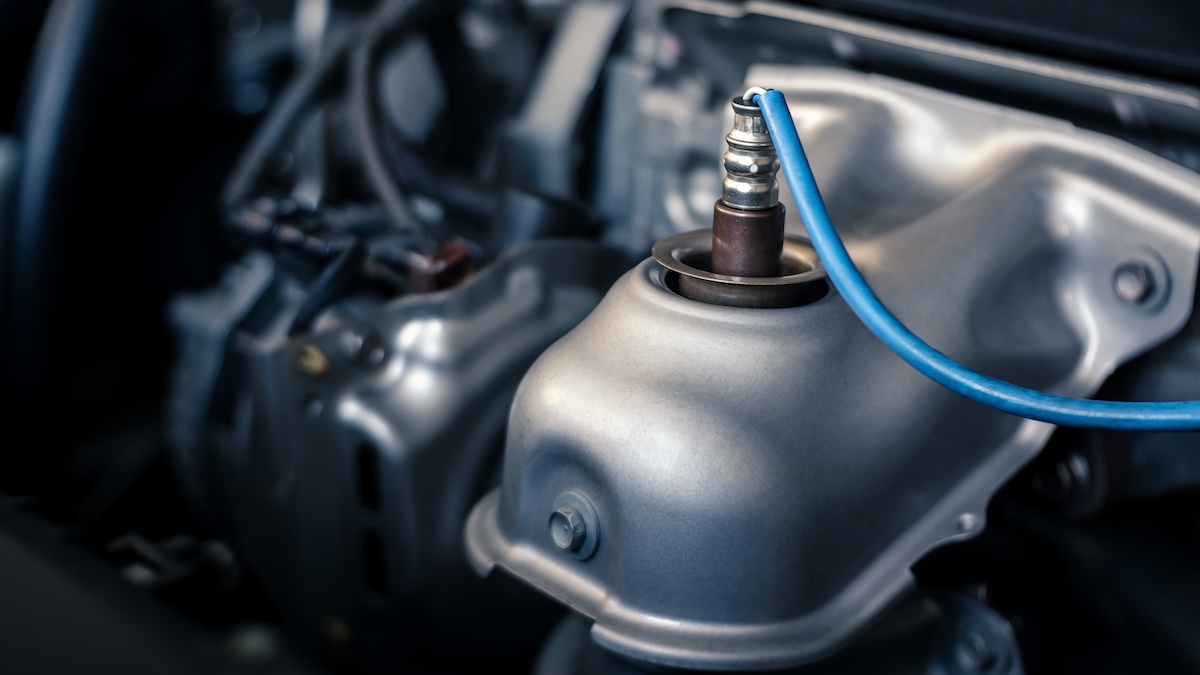
1. Oxygen Sensor
The oxygen sensor, commonly called an O2 sensor, is among the sensors most frequently associated with a check engine light. Its job is to measure the amount of oxygen present in the exhaust gases. The engine control module uses this information to determine whether the air-fuel mixture is too rich or too lean.
Modern gasoline engines often have multiple oxygen sensors, with sensors positioned before and after the catalytic converter. Their readings help the vehicle adjust fuel delivery and monitor the efficiency of the emissions system.
An oxygen sensor can develop problems because it operates in an extremely hot environment. Exhaust temperatures can become high enough to place considerable stress on the sensor and its internal components. Age, contamination, oil consumption, coolant entering the combustion chamber, and fuel-related deposits can also affect its performance.
When the sensor becomes slow or inaccurate, the engine computer may receive readings that do not match expected operating conditions. This can lead to warning lights, poor fuel economy, rough running, or changes in exhaust emissions.
A failed oxygen sensor does not always stop a vehicle from running. In many cases, the engine continues to operate while fuel control becomes less precise. Drivers may notice reduced mileage, sluggish acceleration, an unusual exhaust smell, or inconsistent engine behavior.
A malfunctioning sensor can also cause the engine computer to make inappropriate fuel adjustments. If the mixture remains too rich for an extended period, excessive fuel can contribute to catalytic converter damage and increased emissions.
Diagnostic trouble codes associated with oxygen sensors can provide useful information, but the code alone does not automatically prove that the sensor itself needs replacement. Wiring problems, exhaust leaks, vacuum leaks, fuel system faults, or other engine conditions can create readings that resemble a bad sensor.
A technician should compare live sensor data with other engine parameters and inspect the related wiring and connectors before installing a new component. This approach helps prevent unnecessary repairs.
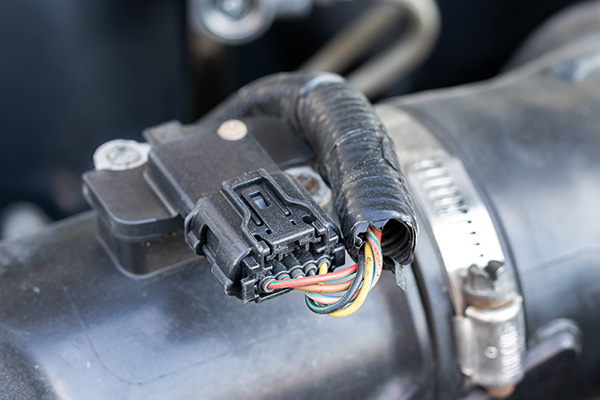
2. Mass Airflow Sensor
The mass airflow sensor, usually called the MAF sensor, measures the amount of air entering the engine. This measurement is important because the engine computer needs to know how much air is available before determining how much fuel to inject.
Many MAF sensors use a heated sensing element that changes temperature as incoming air passes over it. The resulting electrical signal allows the engine control module to estimate airflow and make adjustments to fuel delivery and engine operation.
A MAF sensor can become contaminated by dust, oil vapor, dirt, or particles that pass through the air intake system. Improperly maintained air filters may allow contaminants to reach the sensor.
Certain aftermarket air intake systems can also contribute to contamination if they use filters that allow excessive oil or debris into the intake tract. Once the sensing element becomes dirty, its readings may no longer accurately represent the amount of air entering the engine.
Problems with a MAF sensor can produce several symptoms. The vehicle may hesitate during acceleration, idle roughly, consume more fuel, or experience reduced power.
Some engines may become difficult to start or may stall under certain conditions. A check engine light can appear when the computer detects airflow readings that are outside the expected range or inconsistent with other sensors. Fault codes can point toward airflow measurement problems, but further testing remains important.
A MAF-related trouble code does not automatically mean the sensor is defective. An air leak after the MAF sensor can allow unmetered air into the engine, creating symptoms similar to a faulty sensor.
A restricted air filter, damaged intake hose, electrical problem, or vacuum leak can also interfere with airflow calculations. Technicians may inspect fuel trims, airflow readings, intake components, and wiring to determine the actual source of the problem.
Cleaning may help in some situations when contamination is the cause, but the process must be performed carefully. MAF sensing elements are delicate, and unsuitable cleaning products or physical contact can damage them.
If the sensor has an internal electrical failure, cleaning will not solve the problem. Correct diagnosis is therefore more useful than simply replacing the part whenever a MAF-related code appears.
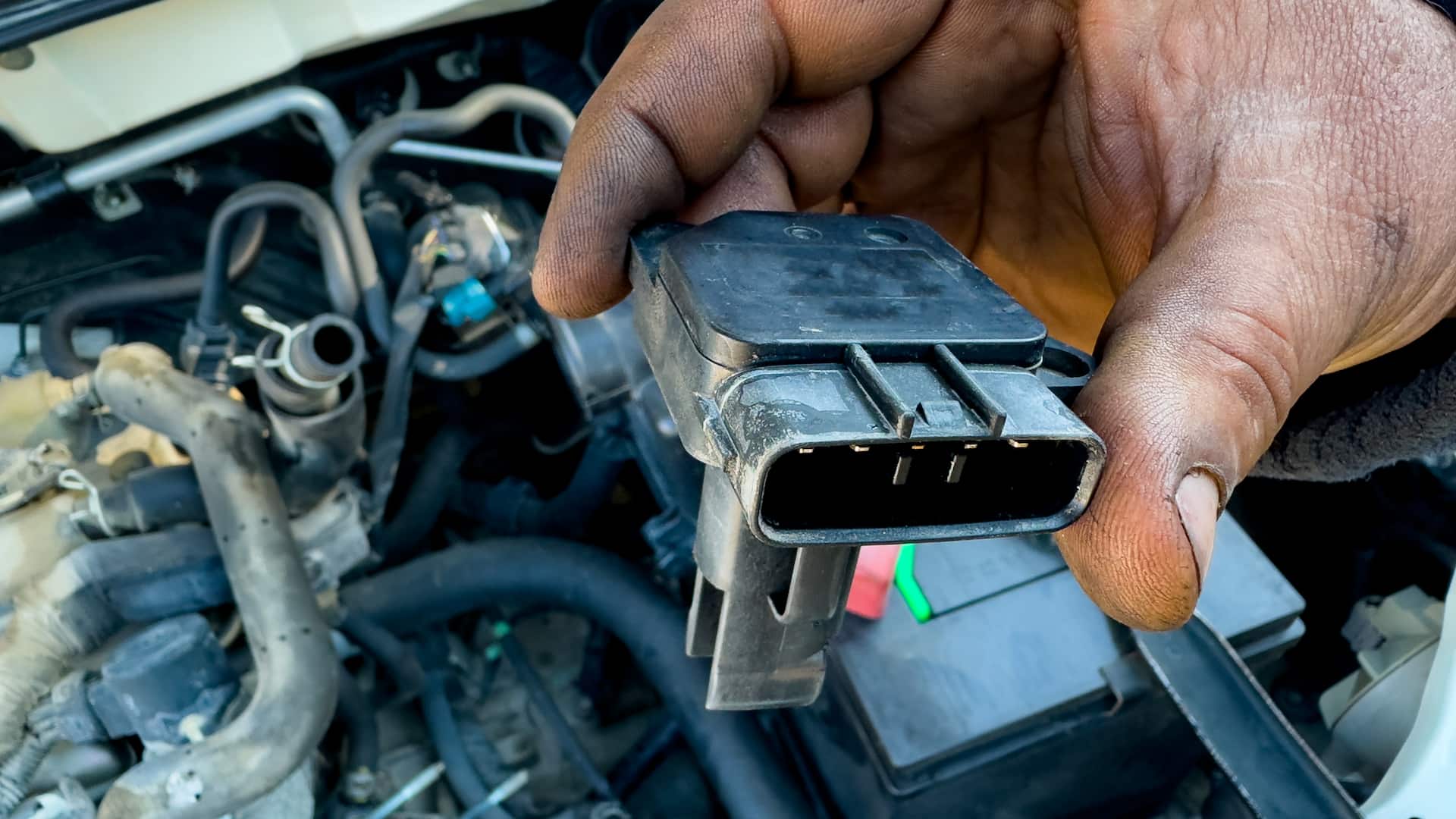
3. Manifold Absolute Pressure Sensor
The manifold absolute pressure sensor, commonly known as the MAP sensor, measures pressure inside the intake manifold. The engine control module uses this information to estimate engine load and determine appropriate fuel delivery and ignition timing.
MAP sensors are particularly important on engines that use manifold pressure as a primary method for calculating incoming air. Their readings can change rapidly as the driver presses or releases the accelerator.
A MAP sensor can cause a check engine light when its readings do not correspond with expected engine conditions. Internal sensor failure, damaged wiring, poor electrical connections, contamination, or problems with the sensor’s pressure passage can interfere with its signal.
Some MAP sensors connect directly to the intake manifold, while others use a small vacuum hose. A cracked or disconnected hose can produce symptoms that resemble a defective sensor.
Symptoms can include rough idle, hesitation, poor acceleration, reduced fuel economy, hard starting, and unusual engine behavior. Because MAP information helps the computer determine engine load, an incorrect reading can affect several aspects of engine operation.
The computer may add too much fuel or too little fuel depending on the signal it receives. In some cases, the vehicle may enter a reduced-performance strategy to protect the engine or maintain basic drivability.
Diagnostic testing should include inspection of the sensor’s electrical connector and wiring. If the vehicle uses a vacuum hose connected to the sensor, that hose should also be checked for cracks, blockage, or disconnection.
Live data from a scan tool can help technicians determine whether the pressure reading changes appropriately as engine operating conditions change. Comparing the signal with expected pressure values can provide additional evidence.
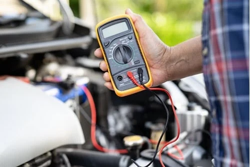
4. Coolant Temperature Sensor
The engine coolant temperature sensor, commonly abbreviated as ECT, tells the engine control module how hot or cold the engine coolant is.
Temperature information influences fuel delivery, ignition strategy, idle control, cooling fan operation, and emissions management. When an engine is cold, it generally needs a different fuel strategy than it does after reaching normal operating temperature. The computer relies on the coolant temperature signal to make these adjustments.
A faulty coolant temperature sensor may report a temperature that is significantly different from the actual coolant temperature. For example, a sensor might incorrectly indicate that the engine is extremely cold even after it has warmed up.
The computer may respond by enriching the fuel mixture longer than necessary. In other situations, an incorrect high-temperature reading can cause the computer to alter fuel and ignition strategies inappropriately.
Drivers may notice difficult starting, poor fuel economy, unstable idle speed, black exhaust smoke, or unusual cooling fan behavior. Some vehicles can experience a warning light without obvious changes in driving performance.
The exact symptoms depend on how the sensor fails and how the vehicle’s control system responds to the faulty signal. A coolant temperature sensor issue can therefore range from an easily noticeable drivability problem to a warning light that appears to be the only symptom.
Testing the sensor involves checking its electrical signal and comparing the reported temperature with actual engine conditions. A scan tool can display the temperature value being reported to the engine computer.
When the engine is cold, the reading should generally be close to the surrounding temperature. As the engine warms, the value should change in a logical manner. Sudden jumps, implausible readings, or a temperature that remains fixed can indicate a problem.
A sensor replacement should also be accompanied by an inspection of the connector, wiring, and cooling system. Low coolant levels or cooling system problems can create separate issues that may be confused with a temperature sensor fault.
Since the coolant temperature signal influences several engine functions, diagnosing the problem correctly can improve drivability and help maintain proper emissions performance.
5. Throttle Position Sensor
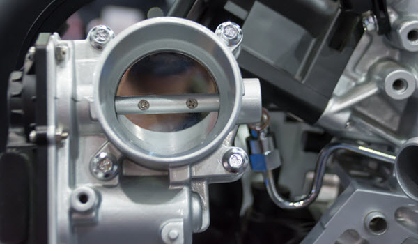
The throttle position sensor, or TPS, monitors the position of the throttle. In older vehicles, it was commonly attached directly to the throttle body and tracked the movement of the throttle plate.
Modern vehicles often use electronic throttle control, where accelerator pedal sensors communicate driver demand to the engine computer, while the throttle body contains position sensors that report actual throttle movement.
The engine control module uses throttle position information for acceleration, fuel delivery, transmission control, idle management, and other functions.
When the computer detects that the throttle position signal is inconsistent, it may illuminate the check engine light. In electronic throttle systems, multiple position signals are often compared to improve reliability. A disagreement between those signals can cause the vehicle to enter a reduced-power mode.
Symptoms of throttle position problems can include hesitation, inconsistent acceleration, unstable idle, poor throttle response, or sudden loss of power.
Some vehicles may limit engine speed when the control module detects a serious electronic throttle problem. This protective strategy can make the vehicle difficult to drive normally and should not be ignored, particularly if the warning light is accompanied by major changes in acceleration.
Electrical faults are important to consider when diagnosing TPS problems. Damaged wiring, loose connectors, corrosion, or problems with the throttle body itself can produce similar trouble codes.
A technician can examine throttle position data while gradually operating the throttle to see whether the signal changes smoothly. An irregular signal can provide evidence of a sensor or throttle assembly problem.
6. Crankshaft Position Sensor
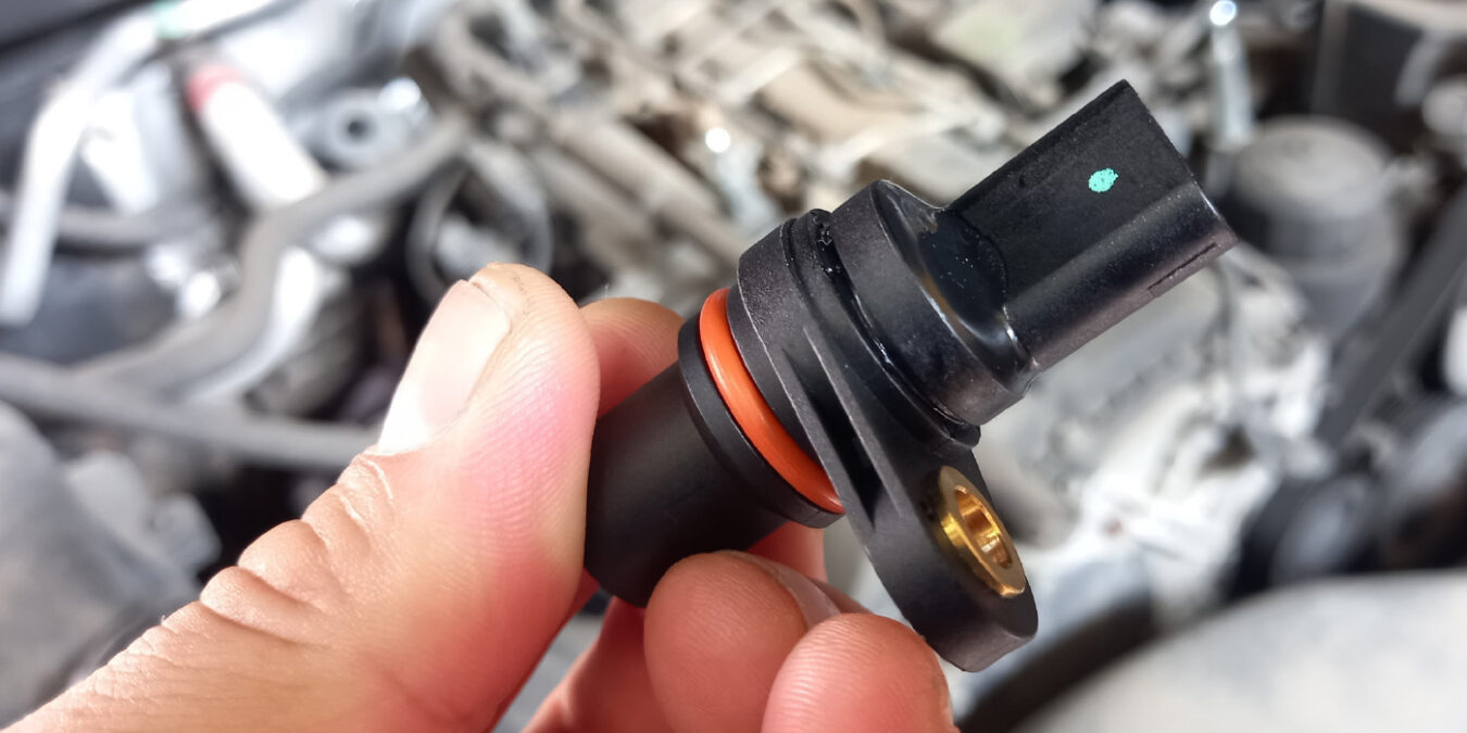
The crankshaft position sensor is critical because it tells the engine control module where the crankshaft is positioned and how quickly it is rotating.
This information allows the computer to coordinate fuel injection and ignition timing. Without a reliable crankshaft signal, the engine computer may be unable to determine the correct timing for combustion. The sensor therefore plays a central role in engine starting and operation.
A failing crankshaft sensor can cause intermittent or complete starting problems. Some vehicles may start normally when cold but fail to restart after the engine becomes hot. Others may stall unexpectedly while driving.
A check engine light may appear if the computer detects an abnormal signal, but a sensor can sometimes fail without immediately producing a warning light. This makes symptom patterns and diagnostic testing particularly important.
Heat, vibration, wiring damage, and internal electrical failure can contribute to crankshaft sensor problems. The sensor is often installed near the crankshaft or another rotating component, exposing it to demanding conditions.
Problems can also arise from damaged reluctor wheels or incorrect sensor positioning. A replacement sensor may not solve the issue if the component it reads has been damaged.
7. Camshaft Position Sensor
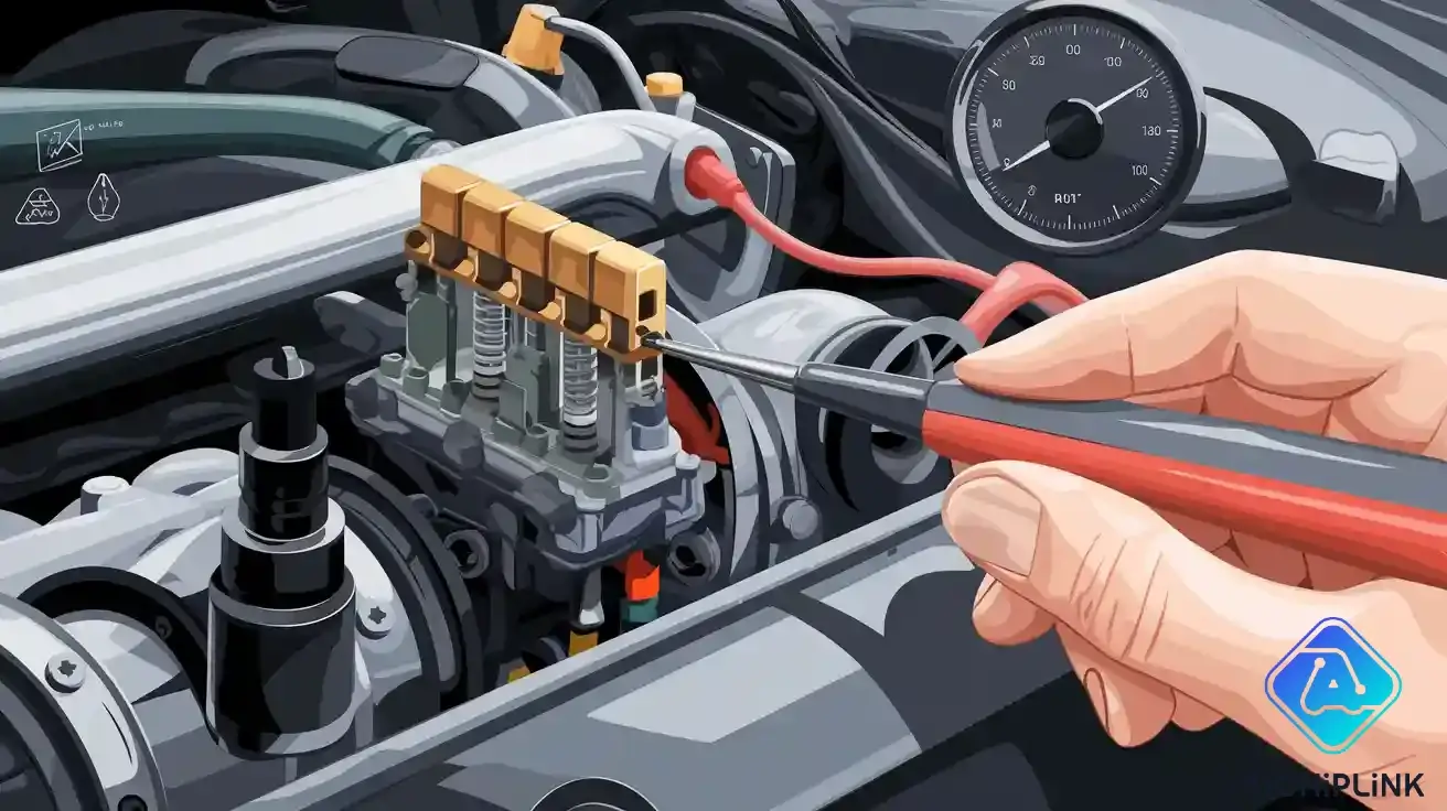
The camshaft position sensor monitors the position and speed of the camshaft. The engine control module uses this information to coordinate fuel injection, ignition timing, variable valve timing, and synchronization between the camshaft and crankshaft.
Many modern engines rely heavily on accurate camshaft information because precise valve timing is important for performance, fuel economy, and emissions.
A failing camshaft sensor may cause difficult starting, rough running, reduced acceleration, or intermittent stalling. Some vehicles can continue running with a faulty signal by using information from other sensors, while others may experience much more severe drivability problems.
The check engine light may appear when the computer detects that the camshaft signal is missing, implausible, or out of synchronization with the crankshaft.
Sensor wiring deserves careful attention during diagnosis. A broken wire, damaged connector, poor ground, or electrical interference can create a sensor code even when the sensor itself is functioning correctly.
Mechanical problems can also cause synchronization errors. A stretched or damaged timing chain, incorrect timing, or a damaged reluctor component can produce readings that look like a camshaft sensor failure.
Diagnostic trouble codes can indicate whether the computer has detected a camshaft signal problem, but they do not always identify the failed component.
A technician may compare camshaft and crankshaft signals, inspect timing data, and verify sensor power and ground circuits. This is particularly important when a vehicle has multiple related codes because a mechanical timing problem may affect several readings at once.
Replacing a confirmed faulty camshaft sensor can improve starting and engine operation. If the sensor code returns after replacement, further investigation is necessary rather than repeatedly installing new sensors. Correct timing, healthy wiring, and proper electrical signals are all required for reliable engine synchronization.
8. Fuel Rail Pressure Sensor
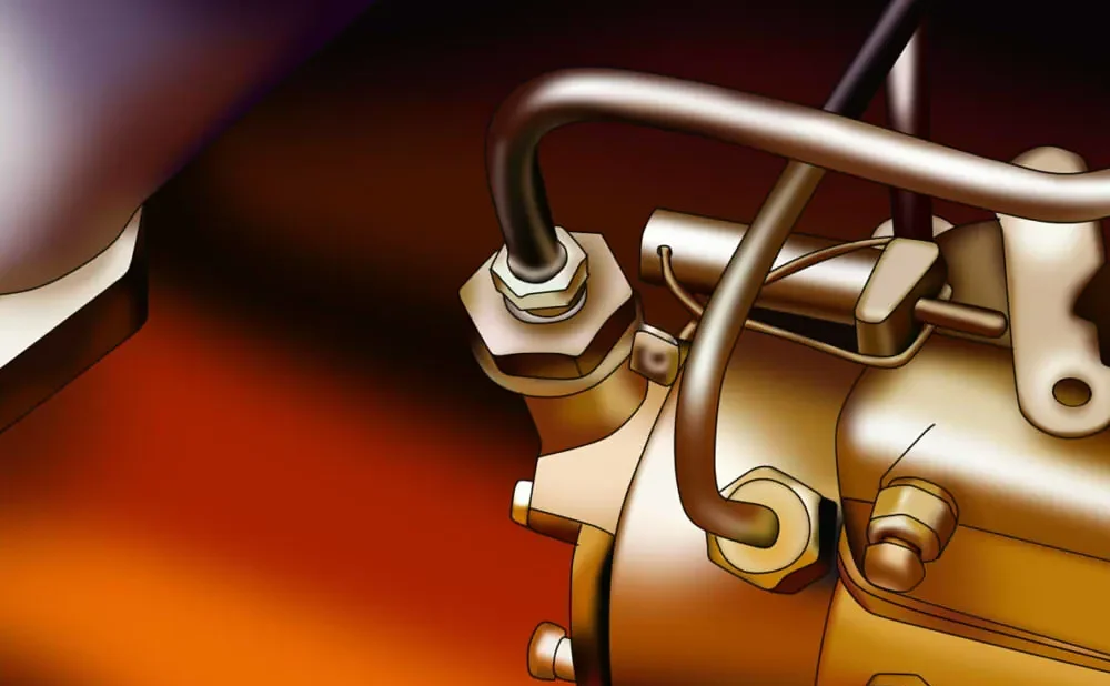
The fuel rail pressure sensor measures pressure in the fuel rail and sends that information to the engine control module. The computer uses this measurement to regulate fuel delivery and determine whether the fuel system is operating within its intended pressure range.
Fuel pressure requirements vary considerably between gasoline direct-injection engines, port-injected engines, and diesel systems, so the sensor’s design and operating range depend on the vehicle.
A faulty fuel pressure sensor can cause hard starting, hesitation, reduced power, rough running, poor fuel economy, or stalling. In some cases, the engine may crank for an extended period before starting.
If the computer receives inaccurate pressure information, it may command inappropriate fuel delivery. A check engine light can appear when the measured value falls outside expected limits or does not respond correctly to changes in operating conditions.
Fuel pressure problems do not always originate with the sensor. A weak fuel pump, restricted fuel filter, wiring issue, faulty pressure regulator, leaking injector, or inadequate electrical supply can create similar symptoms.
For that reason, technicians generally compare the sensor’s reported pressure with actual fuel pressure measurements when appropriate. This comparison can determine whether the sensor is lying about pressure or whether the fuel system itself has a pressure problem.
The sensor’s electrical circuit should also be inspected. Corrosion, damaged wiring, loose terminals, or poor connections can interrupt the signal.
Some fuel pressure sensors are exposed to high-pressure fuel systems, making proper service procedures essential. Technicians should follow manufacturer instructions and use equipment suitable for the specific fuel system rather than treating every pressure sensor as interchangeable.
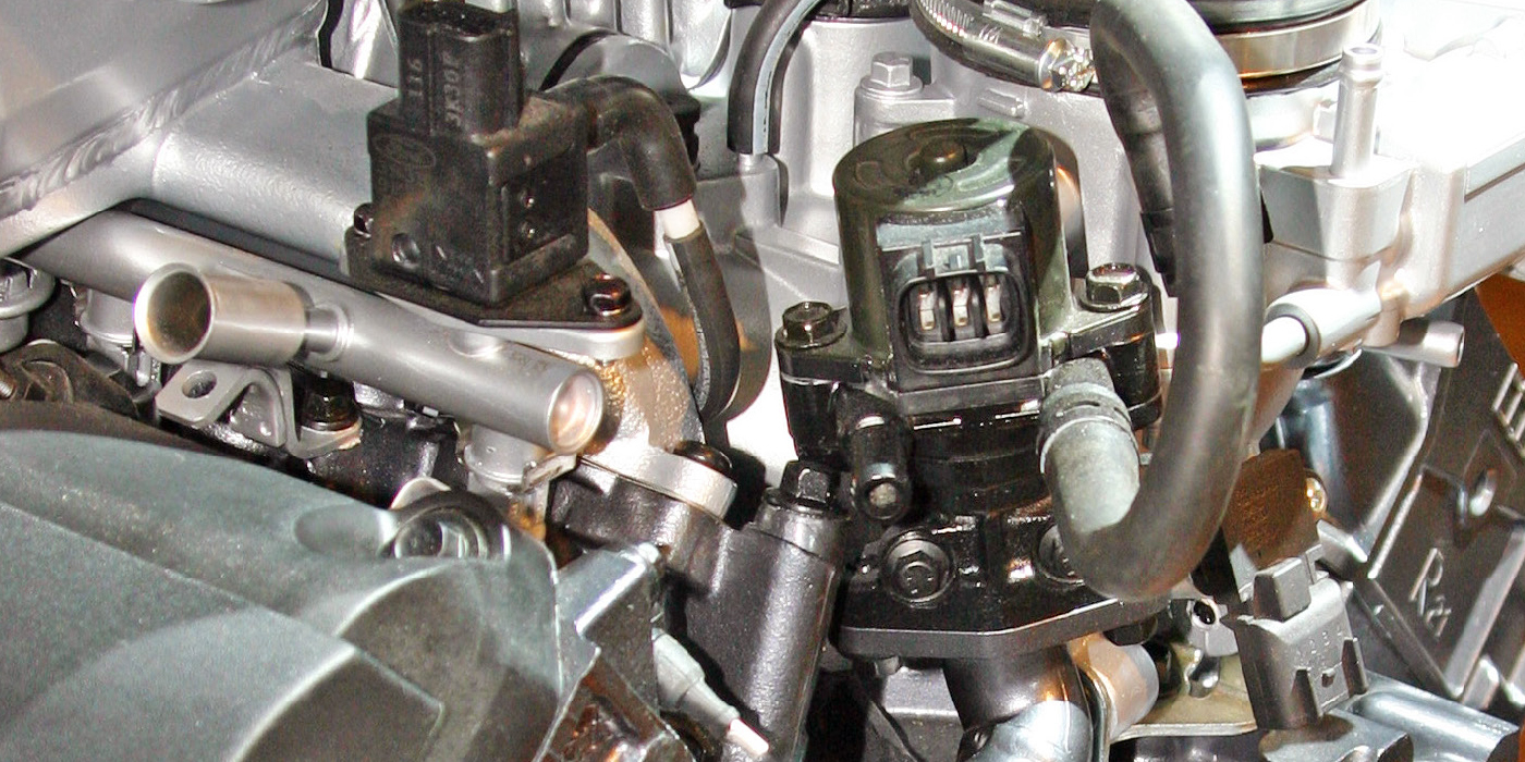
9. Exhaust Gas Recirculation Position Sensor
Exhaust gas recirculation, known as EGR, helps reduce certain nitrogen oxide emissions by routing a controlled amount of exhaust gas back into the engine under appropriate operating conditions.
Many EGR systems include position feedback that tells the engine control module how far the EGR valve has moved. If the reported position does not match the commanded position, the computer can store a diagnostic trouble code and illuminate the check engine light.
Carbon buildup is a common concern with EGR components because exhaust gases contain particulate matter and other deposits. Over time, deposits can restrict movement or prevent the valve from closing properly.
The position sensor can also develop an electrical fault. In some systems, the sensor is integrated into the EGR valve assembly, meaning replacement requirements depend on the manufacturer’s design.
EGR-related symptoms can include rough idle, hesitation, reduced power, increased emissions, or engine performance problems.
A valve that remains open when it should be closed can affect idle quality because excessive exhaust gas enters the intake. A valve that fails to open can prevent the emissions system from operating as intended. The exact symptoms depend on the design of the EGR system and the condition of the valve.
A diagnostic code associated with EGR position does not necessarily mean the position sensor itself is bad. Carbon deposits can prevent the valve from reaching the commanded position, creating a disagreement between actual and expected movement.
Wiring and connector faults can also cause incorrect feedback. Proper diagnosis may require checking valve movement, sensor readings, electrical circuits, and related passages.
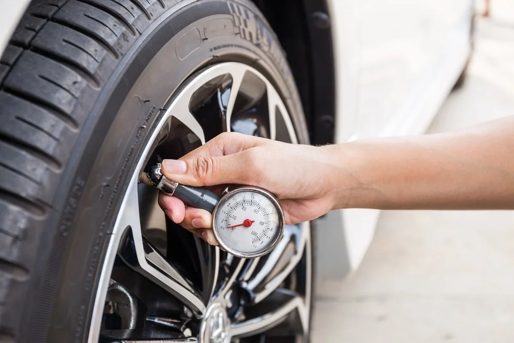
10. Tire Pressure Monitoring Sensor
The tire pressure monitoring system, or TPMS, is worth mentioning because drivers sometimes mistake its warning indicator for a check engine light. TPMS sensors measure tire pressure and communicate with the vehicle’s monitoring system.
Their warning symbol is normally different from the traditional engine-shaped check engine light, but dashboard warning symbols can be confusing, particularly when several indicators appear at the same time.
A TPMS sensor can report low tire pressure, sensor failure, weak battery condition, or communication problems. The sensor is generally installed inside the wheel and is exposed to temperature changes, road impacts, moisture, and tire service.
Its internal battery is not normally designed for simple routine replacement in many sensor designs. When the battery reaches the end of its service life, the complete sensor may need replacement.
Low tire pressure is not necessarily a sensor failure. Pressure naturally changes with temperature, and tires can lose air through punctures, valve problems, or gradual leakage.
The physical tire pressure should therefore be checked with an accurate gauge rather than relying exclusively on the dashboard warning. Correct pressure should be based on the vehicle manufacturer’s recommended specification, generally found on the driver’s door-jamb label or in the owner’s manual.
When a TPMS sensor is replaced, the vehicle may require a relearn or registration procedure. The exact method varies by manufacturer.
Some vehicles can automatically recognize new sensors after driving, while others require a specific reset procedure or diagnostic equipment. A sensor that has been installed but not properly registered may continue to generate a warning.